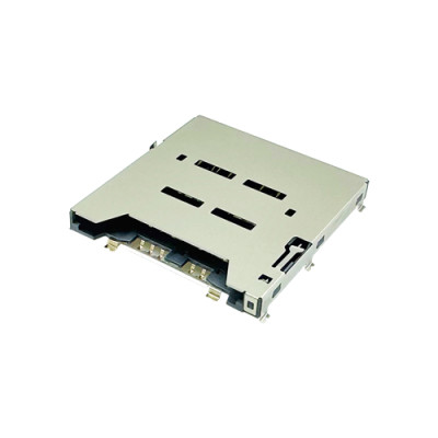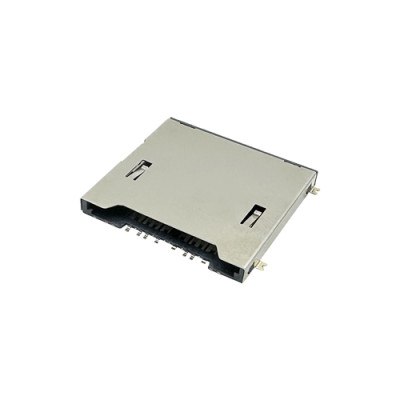
Do you know what professional terms there are for card connectors?
Card connector terminology is compact but not simple: a dozen words carry the whole specification, and a buyer who misreads one of them ends up with a part that passes incoming inspection and fails in the field. This glossary defines the ten terms that appear in every card socket datasheet, in the order they matter when you are comparing parts.
The Ten Terms at a Glance
| Term | What it defines | Typical card socket value |
|---|---|---|
| Terminal | The metal contact that carries current and signal | Phosphor bronze spring contact, 0.1 to 0.2mm stock |
| Contact resistance | Resistance across the mated contact pair | 30mΩ or less |
| Insulation resistance | Leakage across the housing material | 100MΩ and above at 500V DC |
| Insertion / extraction force | Force to seat and release the card | 3 to 25N (national range 5 to 40N) |
| Durability | Mating cycles within specification | 10,000 cycles |
| Polarization | Feature that prevents wrong-orientation insertion | Keyed slot and asymmetric housing |
| Retention force | Force holding the card once seated | Specified against shock and vibration |
| Pitch | Centre-to-centre terminal spacing | 1.27mm on SIM, 1.1mm on microSD |
| Plating | Metal layer on the contact surface | 0.025µm gold over nickel |
| Housing | Insulating body that aligns and protects | LCP, PBT or PA, walls down to 0.05mm |
1. Terminal
The terminal is the metal part that actually touches the card. Card sockets use spring terminals rather than pin-and-socket pairs, so the definition of male and female is less useful here than the distinction between the cantilever spring, which deflects as the card enters, and the landing contact used in IC card readers, which only touches the chip when the card is fully seated. Terminal material is usually phosphor bronze: it holds its spring force better than brass under thermal cycling, which is why it appears in every part rated to 10,000 cycles.
2. Contact Resistance
Contact resistance is the resistance across the mated pair, and it is the number that decides whether a card reads reliably at speed. For card sockets the practical limit is 30mΩ or less. Two clarifications matter when you compare datasheets: whether the figure is a dry-circuit measurement or taken at rated current, and whether it is measured before or after cycling. The same connector can read 18mΩ new and 28mΩ after a thousand insertions, and both numbers are honest.
3. Insulation Resistance
Insulation resistance describes how well the housing blocks leakage between adjacent terminals. It is a material and humidity question more than a design question: LCP absorbs very little moisture and holds its insulation resistance and its dimensions through reflow, which is why it dominates in thin-wall card sockets. PBT and PA are cheaper and adequate where the wall thickness is generous. A part that measures well dry and fails a damp-heat test has a material problem, not a process problem.
4. Insertion and Extraction Force
This is the force the user feels, and it is specified as a window rather than a value. The national range for card sockets is 5 to 40N; MOARCONN holds 3 to 25N, a deliberately narrower window so that the tenth insertion feels like the first and a user with limited hand strength can still seat the card. If the product is used with gloves — automotive, industrial, outdoor — ask for the upper end of the window, not the lower.
5. Durability
Durability is the number of mating cycles over which the connector stays within its electrical specification, which is not the same as the number of cycles before it breaks. A socket rated at 10,000 cycles should still hold 30mΩ or less at cycle 10,000. That is twice the national requirement, and it is the figure that matters for dash cameras, body cameras, test fixtures and any product where the card is swapped weekly.
6. Polarization
Polarization is the geometry that makes wrong-orientation insertion impossible. In a card socket it is a keyed slot, a chamfered corner and an asymmetric housing, sometimes combined with a card-detect switch that only closes when the card is fully and correctly seated. Good polarization is invisible in use and obvious in a teardown: the housing will not accept the card any other way.
7. Retention Force
Retention force keeps the card seated under shock and vibration. It is the specification behind the most common field failure in portable products — a card that walks 0.4mm out of the slot after a drop and loses a data line. Push-push mechanisms rely on the latch, push-pull on friction, and hinge types on spring pressure; all three need a number in the drawing, not just a mechanism name.
8. Pitch
Pitch is the centre-to-centre distance between adjacent terminals, and it sets both the connector size and the PCB process. SIM sockets run 1.27mm pitch, microSD around 1.1mm, and board-to-board connectors used alongside them go down to 0.3mm. Below about 0.5mm, stencil aperture and pad geometry start to matter as much as the connector itself.
9. Plating
Plating is the metal layer on the contact surface, usually gold over a nickel barrier. For card sockets the practical floor is 0.025µm of gold: enough to keep the nickel covered through the rated cycle life and keep contact resistance stable in humid or sulfur-bearing air. Tin plating is cheaper and suitable only for parts that mate once. Silver has the lowest resistance and the fastest sulfidation, which is why it appears in high-current connectors and rarely in card sockets.
10. Housing
The housing is the insulating body that aligns the terminals, guides the card and takes the mechanical load. Material choice follows the process: LCP for thin walls and reflow compatibility, PBT for cost-sensitive parts with thicker walls, PA where toughness matters more than dimensional stability. Wall thickness down to 0.05mm is producible, but every 0.01mm removed makes warpage control harder, and warpage becomes coplanarity failure once the terminals are assembled.
How These Terms Appear in a Real Datasheet
A well-written card socket datasheet ties the terms together instead of listing them. It states contact resistance with the plating specification and the cycle count, gives insertion force as a window with the test method, quotes coplanarity after assembly rather than on the bare part, and names the housing material with its flammability rating. If a datasheet gives you a resistance figure with no plating and no cycle count, the number is not comparable with a competitor's — and the parts are probably custom card socket connectors being quoted from a catalogue page rather than a specification.
Card Connector Terminology FAQ
Is contact resistance the same as insulation resistance?
No, and they fail in opposite directions. Contact resistance is measured across a mated pair and should be low — 30mΩ or less. Insulation resistance is measured between adjacent terminals through the housing and should be high — 100MΩ and above. A connector with a shorted terminal and a connector with a contaminated housing both cause failures, but only one of them shows up as a resistance reading.
What does "mating cycles" actually count?
One complete insertion and removal. A card that is inserted and left in place for a year counts as one cycle. This is why a 10,000-cycle rating on a sealed device is far more generous than it sounds, and why the number matters most for products where the card is swapped weekly.
Why is pitch measured in millimetres rather than inches?
Because the card formats themselves are metric — a microSD card is 15 x 11 x 1.0mm — and because the connector industry for consumer electronics standardized on metric decades ago. Imperial pitch (0.05 inch, or 1.27mm) survives in the SIM socket layout, which is exactly why 1.27mm appears in a metric datasheet.
MOARCONN Quality Anchors
Every MOARCONN card socket connector is validated to 10,000 mating cycles (tested to GB/T 5095.7-1997; over 2× the 3,000–5,000 cycles common in the industry), operates from -45°C to 80°C, and ships with contact resistance ≤30mΩ thanks to ≥0.025µm gold-plated phosphor-bronze terminals. IATF 16949 certified production supports 0 MOQ orders with 7-day sampling and a 25-day development cycle — backed by in-house mold, stamping and injection molding factories and 32 granted patents.