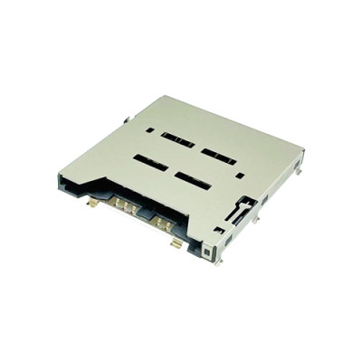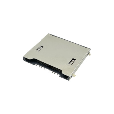
What are the challenges faced by the design of miniaturized card socket connectors?
Miniaturized card socket connectors fail on one of four fronts: space, performance, manufacturing precision, or reliability. Behind those four words sit seven design conflicts that a connector engineer has to resolve before a 1.10mm socket will survive a phone drop, a reflow oven and ten thousand card insertions. This article walks through each conflict and what resolving it actually costs.
1. Material Performance vs Structural Strength
Every gram removed from a housing has to be paid for somewhere else. Thin-wall housings are moulded in high-strength engineering plastics or, on the shell, in ultra-thin stainless steel or a high-strength alloy — and the material then has to survive both corrosion and wear. That is why the contact area is gold plated even when the rest of the terminal is not: the plating is a wear surface, not a cosmetic finish.
The harder problem is the micro spring. A 0.1mm-thick elastic arm has to deliver a stable clamping force inside a cavity only a few tenths of a millimetre deep, and it has to do it without stress concentration at the bend. Too little force and the contact resistance drifts; too much and the arm fatigues at the root after a few thousand cycles. Real designs solve this by tapering the arm rather than thinning it uniformly, and by moving the bend radius out of the highest-stress zone.
2. Manufacturing Precision: Mold, Reflow and Assembly
Molds. A cavity with a 0.05mm wall needs mold tolerances in the micron range, and the harder part is controlling injection deformation afterwards. Warpage in a 0.05mm wall is not a cosmetic defect — it becomes a coplanarity defect once the terminals are assembled into the housing. This is where a connector factory either owns its mold shop or does not: MOARCONN machines molds to ±0.002mm (0.001mm at the limit) and holds injection moulding precision at 0.01mm.
Reflow. A 0.3mm pin pitch has to be compatible with a standard high-precision reflow process without bridging or virtual soldering. The controlling variables are pad geometry, stencil aperture and coplanarity. MOARCONN holds terminal coplanarity at ±0.05mm against a national standard of ±0.10mm, with 0.05mm max full-area solder plane flatness — which is what keeps a 0.3mm pitch part from lifting a pad at the tail end of a panel.
Assembly. Handling a 0.2mm spring contact reliably needs high-precision placement and vision inspection, not manual operation. The parts that fail here fail invisibly: a contact seated 0.05mm high passes a continuity test and fails a drop test three months later.
3. Signal Integrity and EMI in a Smaller Envelope
Miniaturization reduces the conductor cross-section, and a smaller conductor with the same dielectric spacing raises impedance and creates a mismatch at every transition. Above roughly 50MHz this stops being a rounding error. The fixes are the familiar ones applied at a smaller scale: a differential pair for the high-speed lane, a reference plane that is continuous under the connector, and grounding of the metal frame at multiple points rather than one.
The constraint is that none of those fixes may add volume. A shield that improves EMI by 6dB and adds 0.4mm of height has not solved the problem, it has moved it. The practical answer is to make the shell itself the shield — ground it at every mounting tab, stitch vias along the footprint edge, and keep the slot aperture as small as the card format allows.
4. Thermal Management in an Ultra-Thin Body
An ultra-thin design removes the vertical heat path, so heat has to leave laterally through the terminals and the shell. Two levers are available: thermally conductive housing material or metal-matrix composite for the frame, and a pin layout that spreads heat rather than concentrating it under the card. It is worth keeping the problem in proportion — in most card sockets the heat source is the card and the controller beside it, not the connector. The connector's job is to not make it worse, which means avoiding a plastic pocket that traps air around the card.
5. Reliability and Environmental Adaptability
Miniature structures are more vulnerable to external force, because the same drop energy acts on a smaller mass with less material to absorb it. Two countermeasures work: epoxy potting to couple the housing to the board, and reinforcing ribs placed where the housing meets the shell rather than where it looks convenient.
Cycle life is the other half. A micro contact has to survive more than ten thousand insertions, which is a surface-treatment and force-distribution problem rather than a materials-strength problem. A nanoscale gold layer over nickel on phosphor bronze, combined with a contact geometry that spreads pressure across the wipe area instead of concentrating it at one point, is what makes the number achievable. MOARCONN rates 10,000 cycles at 30mΩ or less with plating of at least 0.025µm, across -45°C to 80°C.
6. Compatibility and Standardization
A miniature connector still has to accept a standard card. That means the physical dimensions and protocol of mainstream media — microSD, Nano SIM, eSIM in its MFF2 form — plus the industry specifications behind them, including ISO 7816 and ETSI TS 102 221 for SIM, the SD 3.0 to SD 8.0 family for memory cards, and JEDEC where embedded storage is compared against a socket.
Standardization is also a commercial lever. A connector that suits several devices reduces development cost and shortens the customer's qualification cycle, which is why a supplier with a broad catalogue is faster to work with than one that quotes every project as a new tool. MOARCONN runs 141 card socket models across 13 series for exactly this reason: most requirements are a modification of an existing tool, not a new mold program.
What This Means at Design Review
Six questions catch most of the problems before the board is cut:
- Is the contact force specified as a window, and does the drawing show where the wipe point sits?
- Is coplanarity quoted on the bare part or after reflow, and on what board thickness?
- Does the 0.3mm pitch land pattern match the supplier's recommendation, or a generic one?
- Is there a continuous ground reference under the connector, with no plane split?
- Is the shell grounded at every tab, or only at one corner?
- Is the cycle rating tied to a temperature range and a resistance limit, or quoted alone?
Miniaturized Card Socket Design FAQ
How low can a card socket go before reliability suffers?
Around 1.10mm for a Nano SIM push-pull and 1.28mm for a microSD push-pull is the practical floor for a part that is assembled once and sealed. Below that, the spring arm gets short enough that the force window narrows and insertion feel degrades. The limit is mechanical, not a manufacturing capability — a thinner part can be built, it just behaves differently.
Why does a 0.3mm pitch connector fail AOI after reflow?
Almost always coplanarity measured on the bare connector rather than after assembly, or a stencil and profile qualified on a different board thickness. Ask for the coplanarity figure in writing, verify it at the tail end of the reflow panel where warp is worst, and confirm the pad geometry against the supplier's recommendation.
Does gold plating thickness matter more than contact force?
They fail in different ways and both matter. Plating decides how long contact resistance stays in specification under humidity and thermal cycling; force decides whether the contact stays engaged at all under vibration. A part with thick plating and marginal force passes bench tests and fails in the field, which is why both numbers belong in the specification.
Can a miniature socket be potted for harsh environments?
Yes, but potting changes the thermal path and can wick into the card cavity if the housing is not designed for it. Specify potting at RFQ so the housing geometry includes a dam and the material is compatible with the housing plastic. MOARCONN supports custom housings on a 25-day development cycle with 0 MOQ, which is the right entry point for a potted variant.
MOARCONN Quality Anchors
Every MOARCONN card socket connector is validated to 10,000 mating cycles (2× the national standard), operates from -45°C to 80°C, and ships with contact resistance ≤30mΩ thanks to ≥0.025µm gold-plated phosphor-bronze terminals. IATF 16949 certified production supports 0 MOQ orders with 7-day sampling and a 25-day development cycle — backed by in-house mold, stamping and injection molding factories and 32 granted patents.