Micro SD Card Connector Design Guide: Pinout, PCB Layout, and Selection Tips for Engineers
Micro SD Card Connector Design Guide: Pinout, PCB Layout, and Selection Tips for Engineers
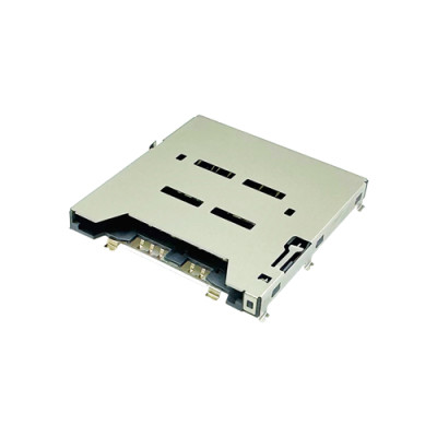
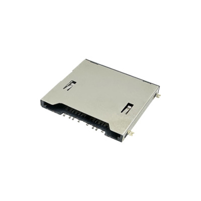
Choosing the right Micro SD Card Connector involves more than matching the card size. Engineers also need to consider pinout, PCB footprint, signal integrity, mechanical clearance, ESD protection, card detection, and connector durability.
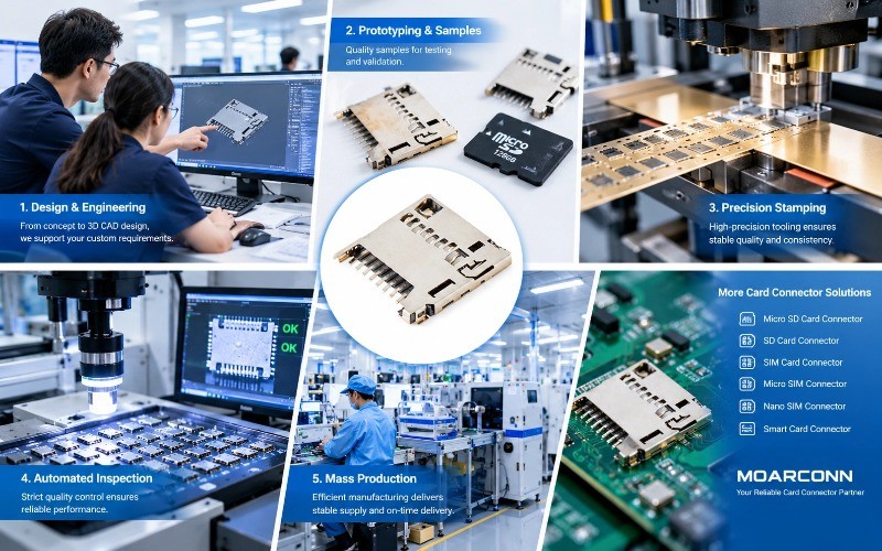
Moarconn provides Micro SD, SD, SIM, and Smart Card Connector solutions for industrial, communication, automotive, consumer electronics, and other applications.
1. Micro SD Card Connector Pinout
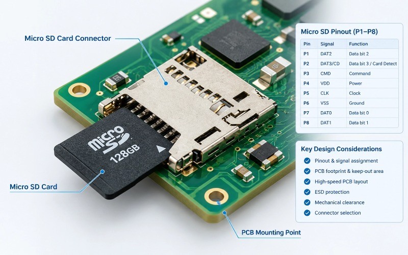
A typical Micro SD interface includes:
| Pin | Signal | Function |
| P1 | DAT2 | Data |
P2 | DAT3/CD | Data / Card Detect |
| P3 | CMD | Command |
| P4 | VDD | Power |
P5 | CLK | Clock |
P6 | VSS | Ground |
P7 | DAT0 | Data |
P8 | DAT1 | Data |
Engineering Note:Card pinout and connector terminal numbering are not always identical. Always use the specific connector manufacturer's datasheet and recommended footprint.
Some advanced connectors may include additional contacts for UHS-II, card detect, power, or ground.
2. How to Choose a Micro SD Card Connector
Engineers should evaluate:
Connector type: push-push, push-pull, or hinged
Top-mount or side-mount configuration
Connector height
PCB footprint
Card-detect switch
Contact plating
Mating cycles
Operating temperature
Vibration and shock requirements
The connector should be selected according to the complete product design rather than price or dimensions alone.
3. Micro SD Connector PCB Footprint
Always start with the manufacturer's recommended footprint.
Check:
Contact pad dimensions
Solder tabs
Mechanical anchors
Keep-out area
Card insertion clearance
PCB edge distance
Enclosure clearance
A connector may fit the PCB footprint but still interfere with the enclosure or other components.
4. Micro SD PCB Layout Guidelines
For reliable high-speed operation:
Keep CLK, CMD and DAT traces short
Maintain a continuous ground reference
Minimize unnecessary vias
Avoid noisy signal areas
Consider trace-length matching where required
Follow the host MCU/SoC routing guidelines
Place ESD protection appropriately
The connector is part of the overall signal path:
Host IC → PCB traces → Connector → Micro SD Card
Good connector selection cannot compensate for poor PCB layout.
5. ESD and Mechanical Reliability
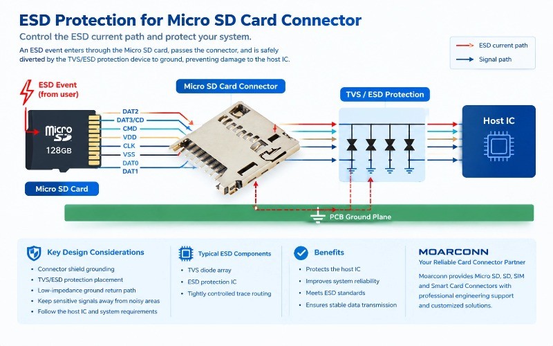
Because Micro SD cards are user-accessible, ESD protection should be considered early in the design.
Engineers should evaluate:
Connector shield grounding
ESD/TVS protection
Ground return path
Contact stability
Insertion/removal cycles
Card retention
Vibration and shock
6. Micro SD Card Connector Selection Checklist
Before production, verify:
Card compatibility
Pin assignment
Recommended PCB footprint
Connector height
Card insertion direction
Card-detect function
Contact resistance and plating
Mating cycles
ESD requirements
Temperature and environmental requirements
SMT compatibility
3D mechanical clearance
7. Micro SD, SIM Card Pinout, and SIM Card Connectors
The same engineering principle applies when designing SIM Card Connectors.
A SIM card pinout commonly includes VCC, RST, CLK, GND, and I/O. However, the connector's physical terminal numbering can vary by product.
Therefore:
Always verify the exact connector datasheet instead of relying on a generic pinout diagram.
Moarconn provides both Micro SD Card Connectors and SIM Card Connectors, allowing engineers to source different card-interface solutions from one connector manufacturer.
8. Why Choose Moarconn?
Moarconn specializes in card connector R&D and manufacturing, including:
Micro SD Card Connectors
SD Card Connectors
SIM Card Connectors
Micro SIM and Nano SIM Connectors
Smart Card Connectors
OEM/ODM customization
Moarconn supports projects from connector selection and DFM review to prototyping, tooling, customization, and mass production.
For projects with unusual PCB dimensions, connector height, insertion direction, card-detect requirements, or mechanical constraints, a customized connector can be considered.
Conclusion
A reliable Micro SD Card Connector should be selected as part of the complete hardware system.
Consider:
Pinout → Footprint → PCB Layout → ESD → Mechanical Reliability → Manufacturing
For Micro SD, SIM, and other card connector requirements, engineers can work with Moarconn to evaluate standard or customized connector solutions based on their PCB and application requirements.