Micro SD Card Connector Selection Guide: How Engineers Choose the Right Connector for PCB Design
Micro SD Card Connector Selection Guide: How Engineers Choose the Right Connector for PCB Design
Choosing a Micro SD Card Connector is not simply a matter of matching the card size. For hardware engineers, the right connector must also fit the PCB footprint, mechanical enclosure, insertion mechanism, electrical requirements, manufacturing process, and expected operating environment.
A connector that looks suitable on a datasheet may still create problems during PCB layout, assembly, testing, or field use.
This engineering guide explains how to select a Micro SD Card Connector systematically—from application requirements and mechanical design to electrical performance, PCB integration, reliability, and production validation.
Engineer’s Rule of Thumb: Select the Micro SD Card Connector based on the complete system requirement, not on connector dimensions alone.
For engineers looking for a supplier that can support both standard and customized requirements, Moarconn manufactures Micro SD, SD, SIM, and related card connectors, with product options covering different mounting methods, ejector mechanisms, profiles, and transmission-speed requirements
Quick Answer: How Do You Choose a Micro SD Card Connector?
Before selecting a specific part number, evaluate these eight factors:
1.Card format and compatibility
2.Connector mechanism
3.Mounting orientation
4.Connector height and PCB footprint
5.Electrical performance
6.Durability and mating cycles
7.Environmental requirements
8.SMT assembly and manufacturing requirements
The selection process should follow this sequence:
Application Requirements → Mechanical Requirements → Electrical Requirements → PCB Integration → Reliability → Manufacturing → Supplier Validation
This approach reduces the risk of selecting a connector that works electrically but fails mechanically, does not fit the enclosure, or creates problems during mass production.
What Is a Micro SD Card Connector?
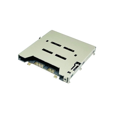
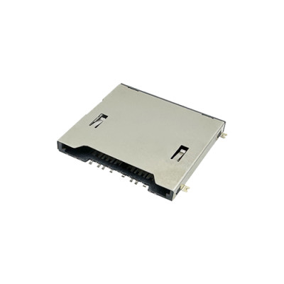
A Micro SD Card Connector is a mechanical and electrical interface that allows a removable micro SD memory card to connect to a host PCB.
The connector has two fundamental functions:
Mechanical:securely hold and guide the micro SD card during insertion, operation, and removal.
Electrical:maintain stable contact between the card contacts and the host circuit.
Micro SD Card Connectors are widely used in compact electronics, embedded systems, IoT devices, industrial equipment, cameras, data loggers, communication equipment, and other products where removable storage is required.
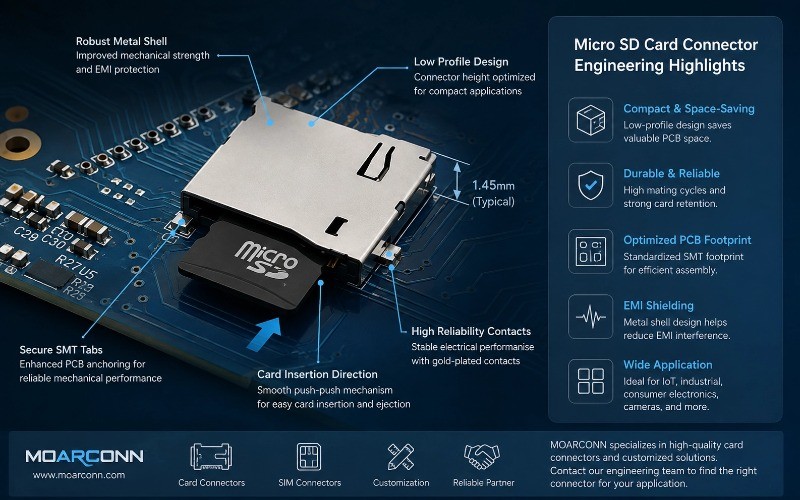
Because space is often limited in these products, connector height, footprint, insertion mechanism, and PCB placement can be just as important as electrical specifications.
1. Start With the Application, Not the Connector
One of the most common mistakes in connector selection is starting with a product catalog and asking:
“Which Micro SD Card Connector is the smallest?”
A better engineering question is:
“What does my product require from the connector?”
The same Micro SD card format can require completely different connector designs depending on the application.
For example:
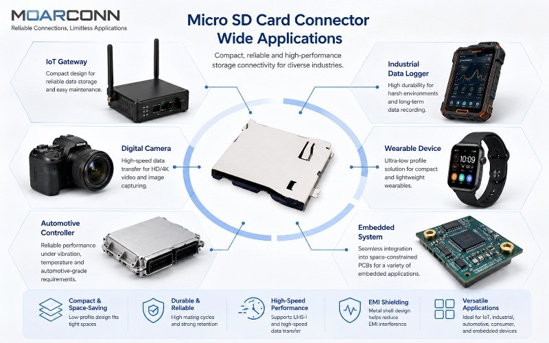
| Application | Primary Design Priority |
| Wearable electronics | Ultra-low profile and compact footprint |
IoT gateway | Compact size and reliable card access |
Industrial data logger | Durability and environmental resistance |
Digital camera | Stable high-speed data transmission |
Automotive electronics | Vibration and temperature performance |
Portable test equipment | Easy insertion and repeated card replacement |
Embedded controller | PCB integration and reliable card detection |
Moarconn's engineering guidance similarly recommends starting with application requirements rather than selecting a generic connector first. The company's current product portfolio includes multiple Micro SD configurations intended for different mechanical and transmission requirements.
Engineer's Checkpoint
Before opening a connector catalog, define:
Available PCB area
Maximum connector height
Card insertion direction
Required mating cycles
Operating temperature
Vibration/shock exposure
Required data-transfer performance
SMT assembly requirements
Card-detect requirements
Expected production volume
2. Choose the Right Micro SD Connector Mechanism
The insertion/ejection mechanism directly affects user experience, mechanical reliability, PCB layout, and product thickness.
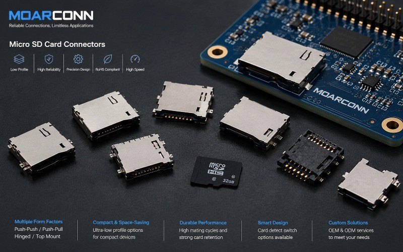
The most common designs include Push-Push,Push-Pull, and Hinged mechanisms.
Push-Push Micro SD Card Connector
A push-push connector uses a press-to-insert and press-to-eject mechanism.
Advantages
Easy one-hand operation
No external ejector required
Clean product appearance
Suitable for compact products
Good integration with enclosed housings
Potential considerations
Requires sufficient internal mechanical clearance
Eject mechanism must be designed for the expected cycle life
Incorrect card alignment can increase mechanical stress
Best suited for:consumer electronics, IoT devices, embedded equipment, portable products, and applications where the card is frequently accessed.
Push-Pull Micro SD Card Connector
A push-pull connector generally allows the card to be inserted and removed directly.
Advantages
Simple mechanical structure
Can support compact layouts
Suitable for applications where card replacement is less frequent
Can be useful when a simple card path is preferred
Potential considerations
Requires sufficient external access
Card retention depends on the specific design
Product enclosure design becomes important
Hinged Micro SD Card Connector
A hinged design secures the card with a hinged cover or locking structure.
Advantages
Strong mechanical retention
Suitable for applications exposed to vibration or movement
Can provide additional protection against accidental card removal
Potential considerations
Requires additional vertical or lateral space
More mechanical components can increase design complexity
Push-Push vs Push-Pull vs Hinged
| Feature | Push-Push | Push-Pull | Hinged |
| User operation | Very convenient | Simple | Secure |
| PCB integration | Excellent | Excellent | Application dependent |
| Compact products | Excellent | Excellent | Moderate |
Frequent access | Excellent | Good | Moderate |
Vibration resistance | Good | Application dependent | Excellent |
Mechanical complexity | Moderate | Low | Higher |
Engineering tip:Do not choose an ejector mechanism based only on user preference. Consider card retention, enclosure clearance, insertion frequency, vibration, and product lifetime together.
3. Check Connector Height Before You Check Price
For compact electronics, connector height can become a major mechanical constraint.
A Micro SD Card Connector may occupy a relatively small PCB area while still creating a significant Z-axis limitation.
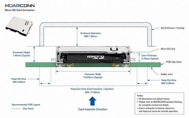
Moarconn's current Micro SD product portfolio includes examples around 1.15 mm, 1.28 mm, 1.45 mm, 1.60 mm, 1.67 mm, and 2.25 mm, illustrating how connector height can vary substantially between designs.
Why Connector Height Matters
The actual mechanical stack-up may include:
PCB + connector + Micro SD card + enclosure + shielding + internal components
Therefore, do not compare connector height in isolation.
Engineer's Z-Height Check
Before finalizing a connector:
1.Measure the available PCB-to-enclosure clearance.
2.Add the connector's maximum height.
3.Consider the inserted card thickness.
4.Check card insertion/ejection movement.
5.Include housing and PCB manufacturing tolerances.
6.Verify the complete assembly using 3D CAD.
4. Top-Mount, Bottom-Mount or Side-Mount?
Mounting orientation can significantly influence PCB layout and enclosure design.
Top-Mount
The connector is mounted on the component side of the PCB.
Benefits
Straightforward PCB integration
Easy component access
Suitable for many standard layouts
Bottom-Mount
The connector is positioned beneath the PCB.
Benefits
Can optimize top-side component space
Useful for specific enclosure configurations
Can help separate the card from other components
Design considerations
PCB thickness
Bottom-side component clearance
Assembly process
Card accessibility
Enclosure geometry
Side-Mount
The card is inserted from the side of the product.
Benefits
Convenient external access
Can optimize internal PCB space
Useful for compact handheld products
Moarconn's selection guidance specifically identifies mounting orientation as an important design factor because top-, bottom-, and side-mount configurations affect product form factor and PCB layout.
5. Verify the PCB Footprint Before Approving the Connector
A connector can be mechanically compatible with a product but still create PCB design problems.
Before approving a Micro SD Card Connector, verify the manufacturer's recommended footprint.
Key PCB Parameters
5.1 Contact Pad Geometry
Check:
Pad length
Pad width
Pitch
Contact alignment
Solder mask opening
Do not create a generic footprint based only on the connector's external dimensions.
5.2 Mechanical Solder Tabs
Micro SD connectors experience mechanical forces during card insertion and removal.
Therefore, mechanical solder tabs or anchoring structures should be evaluated separately from electrical contacts.
5.3 Keep-Out Area
Check clearance for:
Micro SD card insertion
Ejection mechanism
Connector housing
Metal shield
Nearby components
Product enclosure
5.4 Locating Features
Locating pins or locating structures can improve connector positioning during SMT assembly and help maintain consistent alignment.
5.5 3D Clearance
Always check the connector in the actual mechanical assembly.
A 2D PCB footprint may appear correct while the physical connector interferes with:
Battery
Housing
Display
RF shield
Cable
Adjacent components
6. Evaluate Electrical Performance
A Micro SD Card Connector is part of the signal path. For higher-speed applications, connector selection should therefore be considered together with PCB routing and signal integrity.
Moarconn's current product range includes Micro SD solutions categorized around 104 MB/s, 300 MB/s and 985 MB/s transmission levels, while its engineering guidance highlights contact resistance, signal integrity, impedance control and shielding as important considerations.
Contact Resistance
Low and stable contact resistance helps maintain reliable electrical connection.
When comparing products, look at:
Initial contact resistance
Resistance stability
Contact force
Contact material/plating
Long-term wear
Contact Plating
For applications requiring repeated insertion or long-term contact stability, contact plating should be evaluated carefully.
Important considerations include:
Corrosion resistance
Wear resistance
Electrical conductivity
Expected mating cycles
Environmental conditions
High-Speed Applications
As signal speed increases, PCB routing and connector design become increasingly important.
Consider:
Trace length
Trace geometry
Ground return path
Impedance control
Via count
Crosstalk
Connector grounding
ESD protection
Engineering Principle
The connector cannot be evaluated independently from the PCB transmission path.
A high-performance connector cannot compensate for poor PCB routing, poor grounding, or an unsuitable system-level design.
7. Consider Card Detect Requirements
Some applications need the system to know whether a Micro SD card is inserted.
A connector with a card-detect swWhy Card Detect Can Be Useful
Why Card Detect Can Be Useful
It can allow firmware to:
Detect card insertion
Detect card removal
Start initialization
Safely stop data access
Trigger user notifications
Manage power states
Questions for Engineers
Before selecting a connector with card detect, verify:
Is card detection required?
What switch configuration is required?
Is the switch normally open or normally closed?
What is the switch rating?
How will the signal be connected to the MCU?
Does the connector footprint provide enough PCB space?
8. Check Durability and Mating Cycles
A Micro SD Card Connector is often subjected to repeated insertion and removal.
The connector therefore needs to be evaluated as a mechanical component, not just an electrical interface.
Key Reliability Parameters
Check:
Insertion force
Withdrawal force
Retention force
Mating cycles
Contact wear
Housing strength
Ejector mechanism durability
For industrial or frequently accessed products, cycle life can become a critical selection criterion. Moarconn's engineering checklist highlights the importance of evaluating durability and notes connector options rated for thousands of insertion cycles, while its published selection guidance references 5,000–10,000-cycle ranges for demanding applications.
Don't Ask Only:
“How many cycles does the connector support?”
Also ask:
“How many insertion/removal operations will this product experience during its expected lifetime? ”
A simple estimation can be:
Required connector life = expected annual card operations × product service life × safety margin
The actual safety margin should be determined according to your product risk assessment and validation requirements.
9. Environmental Requirements Matter
The best Micro SD Card Connector for a consumer product may not be the best connector for an industrial device.
Evaluate the operating environment before selecting the connector.
Temperature
Check:
Operating temperature
Storage temperature
Thermal cycling
Material stability
Humidity
For humid environments, evaluate:
Contact corrosion
Housing material
Shield construction
Sealing requirements
Vibration and Shock
For industrial and automotive applications, evaluate:
Card retention
Contact stability
Housing strength
Solder joint mechanical strength
Ejector mechanism
Dust and Contamination
Where removable cards are externally accessible, contamination can affect contact reliability.
Potential design strategies include:
Appropriate housing design
Protected card opening
Suitable contact materials
System-level enclosure protection
Moarconn states that its SD connector products are tested for thermal shock, humidity and mechanical stress, supporting applications where long-term mechanical and environmental reliability is important.
10. Micro SD Card Connector Selection by Application
Different products require different priorities.
| Application | Recommended Priority | Connector Characteristics to Evaluate |
| Wearables | Size | Ultra-low profile, compact footprint |
| IoT | Size + reliability | Low profile, card detect, SMT |
| Low profile, card detect, SMT | Durability | High mating cycles, mechanical retention |
Camera | Signal integrity | High-speed capability, stable contacts |
Automotive electronics | Environment | Temperature, vibration, retention |
Portable equipment | User experience | Push-push/push-pull mechanism |
Embedded controller | PCB integration | Footprint, height, card detect |
Communication equipment | Communication equipment | Signal integrity, grounding, shielding |
11. A Practical Micro SD Card Connector Selection Checklist
Before releasing the connector into production, engineers should verify the following.
Mechanical
Connector height verified
PCB footprint verified
Mounting orientation confirmed
Card insertion direction confirmed
Card retention verified
Insertion force verified
Withdrawal force verified
Required mating cycles verified
Enclosure clearance verified
Electrical
Contact resistance verified
Contact plating verified
Current/voltage ratings verified
Pin configuration verified
Card-detect requirements verified
High-speed requirements verified
Grounding strategy verified
EMI/ESD requirements reviewed
PCB & Manufacturing
Manufacturer-recommended footprint used
Keep-out area checked
Mechanical anchors verified
SMT compatibility confirmed
Reflow process reviewed
3D CAD interference checked
Component placement verified
Production tolerance reviewed
Reliability
Temperature requirements verified
Humidity requirements verified
Vibration requirements verified
Shock requirements verified
Prototype testing completed
Contact wear evaluated
Qualification testing completed where required
12. Common Micro SD Card Connector Selection Mistakes
Mistake 1: Choosing the Smallest Connector
Smaller is not always better.
A very low-profile connector may introduce compromises in:
Card access
Mechanical retention
Contact force
Assembly
Enclosure clearance
Choose the smallest connector that satisfies the complete system requirement—not simply the smallest connector available.
Mistake 2: Selecting by Price Before Specification
The connector represents only one part of the product's lifecycle cost.
A cheaper connector can become expensive if it causes:
PCB redesign
Assembly problems
Field failures
Contact failures
Product returns
Supply interruptions
Mistake 3: Ignoring the PCB Footprint
Always use the manufacturer's recommended PCB layout and verify it against the latest datasheet.
Mistake 4: Ignoring Card Insertion Clearance
The connector itself may fit the PCB, while the Micro SD card and eject mechanism do not fit the enclosure.
Always check the complete mechanical assembly.
Mistake 5: Choosing a Connector Without Considering Production
A connector that works in a prototype may not necessarily be ideal for mass production.
Consider:
SMT process
Pick-and-place
Packaging
Reflow
Mechanical alignment
Supply continuity
Quality control
13. How Moarconn Helps Engineers Select the Right Micro SD Card Connector
Selecting a connector is easier when the supplier can provide more than a product catalog.
Moarconn specializes in card connector design and manufacturing, including Micro SD Card Connectors, SD Card Connectors, SIM Card Connectors, and related card-interface solutions. Its product categories cover different ejector mechanisms, mounting methods, functions, and transmission-speed requirements.
Standard Micro SD Connector Options
Moarconn's current Micro SD portfolio includes examples such as:
Push-Push Micro SD connectors
Push-Pull Micro SD connectors
Low-profile designs
Top-mount configurations
UFS/UHS-compatible products
Different connector heights
Published examples include a 1.28 mm Push-Push design, 1.15 mm Push-Pull designs, a 1.45 mm Push-Push design, a 1.60 mm UFS/UHS 3-in-1 design, and Micro SD solutions listed for up to 985 MB/s transmission. Actual suitability should always be confirmed against the current product datasheet and application requirements.
Customization for PCB and Mechanical Requirements
Not every application can use an off-the-shelf connector.
Moarconn's published engineering guidance highlights customization of parameters such as:
Connector height
Pin layout
Housing materials
Mechanical configuration
PCB requirements
This can be particularly useful for OEM/ODM projects where a standard connector does not fit the available PCB or enclosure.
14. From Connector Selection to Prototype: Moarconn Engineering Support
A good connector supplier should help engineers answer questions beyond:
“What is the unit price?”
For a new Micro SD Card Connector project, the engineering discussion should include:
Step 1 — Define the Application
Share:
Product type
PCB dimensions
Enclosure constraints
Card access requirements
Operating environment
Step 2 — Define the Mechanical Requirements
Confirm:
Connector height
Mounting direction
Eject mechanism
Card retention
Mating-cycle requirement
Step 3 — Define the Electrical Requirements
Confirm:
Interface
Data rate
Contact requirements
Card detect
EMI/ESD considerations
Step 4 — Review PCB and CAD Data
Verify:
Footprint
Keep-out
3D clearance
Component interference
Assembly requirements
Step 5 — Prototype and Validate
Evaluate:
Card insertion/ejection
Mechanical retention
Contact reliability
Electrical performance
Environmental performance
Step 6 — Prepare for Mass Production
Confirm:
Manufacturing process
Quality requirements
Packaging
Production capacity
Supply continuity
Moarconn states that it supports both prototype and mass-production requirements and provides customized card-connector solutions for different PCB and mechanical needs.
Recommended CTA:
Need help selecting a Micro SD Card Connector for your PCB?
Share your PCB dimensions, required connector height, mounting orientation, card-detect requirement, and application environment with the Moarconn engineering team. We can help identify a suitable standard solution or discuss a customized connector design.
Request a Micro SD Card Connector Solution from Moarconn
15. Frequently Asked Questions About Micro SD Card Connectors
What is a Micro SD Card Connector?
A Micro SD Card Connector is a PCB-mounted mechanical and electrical interface used to connect a removable Micro SD memory card to an electronic system.
How do I choose a Micro SD Card Connector?
Start with the application requirements. Then evaluate connector mechanism, mounting orientation, height, PCB footprint, electrical performance, durability, environmental conditions, and manufacturing requirements.
What is the difference between Push-Push and Push-Pull Micro SD Connectors?
A Push-Push connector uses a press-to-insert and press-to-eject mechanism, while a Push-Pull design generally allows the card to be inserted and removed directly. The appropriate choice depends on product space, user access, mechanical requirements, and expected card replacement frequency.
How important is connector height?
Very important for compact products. A difference of less than 1 mm can affect enclosure clearance, card accessibility, and the overall mechanical stack-up.
Should I choose a Micro SD Connector with card detect?
Choose a card-detect version when the host system needs to detect card insertion/removal through a dedicated mechanical switch.
How many insertion cycles should a Micro SD Connector support?
It depends on the product. Calculate expected card insertion/removal operations over the product's service life and select a connector with an appropriate durability rating and validation margin.
Can a Micro SD Card Connector be customized?
Depending on the supplier and project requirements, customization may be available for parameters such as connector height, pin configuration, housing, mounting configuration, and other mechanical requirements. Moarconn specifically promotes customized card-connector solutions for PCB and mechanical requirements.
What should I check before creating the PCB footprint?
Always start from the connector manufacturer's latest mechanical drawing and recommended PCB layout. Verify contact pads, mounting/anchor pads, keep-out areas, locating features, card insertion clearance, and 3D mechanical interference.
Final Engineering Takeaway
The right Micro SD Card Connector is not necessarily the smallest, cheapest, or highest-speed connector.
It is the connector that provides the right balance of:
Mechanical Fit + Electrical Performance + Reliability + PCB Integration + Manufacturability
A practical selection process is:
Define the application → Select the connector mechanism → Verify height and footprint → Check electrical performance → Evaluate reliability → Validate PCB integration → Test the prototype → Approve for production
For engineers developing compact, industrial, IoT, automotive, or high-performance embedded products, this approach can reduce PCB redesigns, mechanical conflicts, assembly problems, and long-term reliability risks.
If you already have a PCB drawing, enclosure constraint, or target connector specification, contact Moarconn to discuss a suitable Micro SD Card Connector solution, including standard and customized options.
About Moarconn
Dongguan Moarconn Electronic Co., Ltd. specializes in precision card connectors, including Micro SD Card Connectors, SD Card Connectors, SIM Card Connectors, and related interface products.
Moarconn's published product portfolio covers multiple connector mechanisms, mounting configurations, profiles, and transmission-speed categories, while its engineering resources focus on practical connector selection, PCB integration, reliability, and customized OEM/ODM requirements.
Explore Moarconn Micro SD Card Connector Solutions