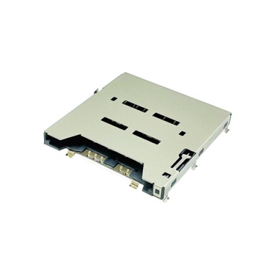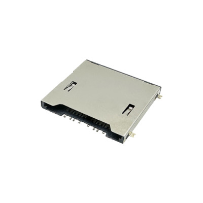
Nano SIM Card Connectors: Types, Features, Specifications, and Selection Guide
Nano SIM Card Connectors: Types, Features, Specifications, and Selection Guide
Primary Keyword:Nano SIM Card Connectors
Secondary Keywords:Nano SIM Connector, Nano SIM Card Socket, Nano SIM Holder, Nano SIM Connector Types, Nano SIM Connector Specifications
Meta Title:Nano SIM Card Connectors: Types, Features & Selection Guide
Meta Description:Learn about Nano SIM card connector types, key specifications, PCB design considerations and selection tips for IoT, industrial and automotive applications.
Introduction
Nano SIM Card Connectors are essential components in electronic devices requiring cellular connectivity. They provide the electrical and mechanical interface between a Nano SIM card and the device's PCB.
Common applications include IoT gateways, GPS trackers, industrial equipment, smart wearables and automotive telematics systems.
Choosing the right connector involves more than matching the SIM card size. Engineers must consider mounting height, insertion mechanism, contact configuration, card detection, mechanical retention and operating conditions.
MOARCONN specializes in card socket connectors, including Nano SIM, Micro SIM, SD and Micro SD connectors. We offer various connector structures and low-profile designs to meet different mechanical, electrical and manufacturing requirements.
This guide covers the main Nano SIM connector types, key specifications and practical selection considerations.
1. What Is a Nano SIM Card Connector?
A Nano SIM Card Connector, also called a Nano SIM socket or Nano SIM card holder, is an electromechanical component that connects a Nano SIM card to an electronic device's PCB.
It allows the cellular module or processor to access the SIM card's subscriber information and communicate with mobile networks.
1.1 Nano SIM (4FF) Dimensions
Nano SIM is also known as the Fourth Form Factor (4FF).
| Parameter | Specification |
| SIM Format | 4FF |
Length | 12.3 mm |
Width | 8.8 mm |
| Thickness | 0.67 mm |
| Standard Contacts | 6 |
Note that SIM card dimensions are different from connector dimensions, which vary by product design.
1.2 How Does It Work?
When a Nano SIM card is inserted:
1.The card enters the connector.
2.Internal spring contacts align with the SIM card pads.
3.Mechanical pressure maintains electrical contact.
4.The cellular module communicates with the SIM card.
5.An optional detection switch identifies card insertion or removal.
Reliable electrical contact and mechanical retention are essential for stable operation.
2. Different Types of Nano SIM Card Connectors
Nano SIM connectors are available in several mechanical designs. The four common configurations are Push-Push, Push-Pull, Hinged and Tray-Type.
2.1 Push-Push Nano SIM Connectors
Push-Push connectors use a spring-loaded locking mechanism. Pushing the card or tray inward locks it, while pushing again releases it.
Key Features:
Push-to-insert and push-to-eject operation.
Convenient card replacement.
Integrated mechanical locking.
Suitable for accessible SIM card slots.
Typical Applications: Cellular routers, IoT gateways, GPS trackers and portable communication devices.
Design Consideration: Engineers should evaluate ejector clearance, card retention force and mechanical durability.
2.2 Push-Pull Nano SIM Connectors
Push-Pull connectors allow users to manually insert and remove the card or tray.
Key Features:
Simple insertion and removal.
Compact mechanical structure.
Suitable for low-profile designs.
Available in space-saving configurations.
Typical Applications:Wearables, compact IoT devices, handheld equipment and GPS trackers.
Design Consideration:Check card retention, accessibility and enclosure clearance.
MOARCONN offers low-profile Push-Pull Nano SIM connectors with product heights of 1.10 mm and 1.20 mm.
2.3 Hinged Nano SIM Connectors
Hinged connectors feature a movable cover or locking frame that opens for card installation and closes to secure the SIM card.
Key Features:
Secure card positioning.
Convenient factory installation.
Suitable for applications requiring infrequent card replacement.
Typical Applications: Industrial equipment, smart meters, embedded communication modules and security devices.
Design Consideration: Evaluate hinge durability, cover retention and closing force.
MOARCONN offers a Hinged Nano SIM connector with a listed height of 1.43 mm.
2.4 Tray-Type Nano SIM Connectors
Tray-type connectors use a removable tray to hold the SIM card before insertion.
Key Features:
Defined card positioning.
Convenient card handling.
Compatible with selected enclosure designs.
Typical Applications:Communication equipment, portable electronics and cellular networking products.
Design Consideration:Check tray dimensions, insertion direction, retention and enclosure clearance.
2.5 Comparison of Connector Types
| Type | Main Advantage | Key Consideration |
| Push-Push | Convenient push-to-eject | Internal mechanism clearance |
Push-Pull | Compact and simple | Card retention |
Hinged | Secure card positioning | Hinge durability |
Tray-Type | Defined card positioning | Tray clearance |
The best connector depends on the device structure, assembly method and maintenance requirements.
3. Key Features of Nano SIM Card Connectors
When selecting a Nano SIM connector, engineers should evaluate the following features.
3.1 Card Detection Switch
A card detection switch allows the host device to identify whether a SIM card is inserted.
Important considerations include:
Normally Open (NO) or Normally Closed (NC) configuration.
Switch electrical ratings.
Pin assignment.
Compatibility with the host circuit.
Card detection does not automatically guarantee hot-plug support. The host controller and firmware must also support safe insertion and removal.
3.2 Contact Design and Plating
Contact design directly affects electrical stability and connector durability.
Important parameters include contact geometry, spring force, contact material, plating and contact resistance.
Gold plating is commonly used because of its corrosion resistance and stable electrical contact characteristics.
3.3 Mechanical Retention and Anti-Misinsertion
The connector should hold the SIM card securely and prevent incorrect insertion.
These features are particularly important in portable, industrial and automotive devices exposed to vibration or repeated handling.
3.4 Metal Shielding and Grounding
Some connectors feature metal housings that provide mechanical protection and a grounding path.
Engineers should verify the shell grounding arrangement and PCB layout. Actual EMI performance depends on the complete device design.
4.Nano SIM Card Connector Specifications
Before selecting a connector, review the following specifications in the manufacturer's datasheet.
4.1 Dimensions and Mounting Height
Connector height is critical for compact electronic products.
Other dimensions to check include:
Connector length and width.
PCB footprint.
Card insertion clearance.
Ejector or hinge movement space.
Enclosure clearance.
MOARCONN Nano SIM Connector Examples
| Connector Type | Connector Type |
| Push-Pull | 1.10 mm |
Push-Pull | 1.20 mm |
Push-Push | 1.37 mm |
| Hinged | 1.43 mm |
These dimensions represent selected MOARCONN products, not universal connector standards.
Always refer to the official mechanical drawing before PCB design.
4.2 Contact Configuration and Pin Assignment
A standard Nano SIM interface uses six electrical contacts.
| Contact | Function |
| C1 | VCC |
C2 | RST |
C3 | CLK |
C5 | GND |
| C6 | VPP |
| C7 | I/O |
Some connectors also include additional terminals for card detection or mechanical functions.
Always verify pin numbering and orientation against the manufacturer's datasheet to avoid PCB layout errors.
4.3 Electrical Specifications
Check the following parameters:
Contact resistance.
Rated current and voltage.
SIM supply voltage compatibility.
Contact plating specifications.
These parameters should meet the requirements of the host SIM interface.
4.4 Operating Temperature and Durability
For industrial, outdoor and automotive applications, check the specified operating temperature range.
Mechanical durability is usually measured by insertion and withdrawal cycles.
Other factors include insertion force, withdrawal force, contact resistance after testing and locking performance.
4.5 PCB Mounting Method
Nano SIM connectors may use different mounting structures.
SMT (Surface Mount Technology)
Supports automated PCB assembly.
Suitable for compact designs.
Compatible with high-volume production.
DIP / Through-Hole Mounting
Uses terminals inserted into PCB holes.
Provides different mechanical attachment characteristics.
Suitable for specific PCB and assembly requirements.
Choose the mounting method according to the connector design and PCB manufacturing process.
5. How to Choose the Right Nano SIM Card Connector
Selecting the right connector requires balancing mechanical, electrical and manufacturing requirements.
5.1 Define PCB Space and Height
Check the maximum mounting height, PCB footprint, surrounding components and enclosure clearance.
For compact products, low-profile Push-Pull connectors may be worth considering.
For example, MOARCONN offers a 1.10 mm Push-Pull Nano SIM connector for space-constrained designs.
5.2 Choose the Insertion Mechanism
| Application Requirement | Recommended Type to Evaluate |
Push-to-eject operation | Push-Push |
| Compact card access | Push-Pull |
| Factory-installed SIM | Hinged |
| Removable card tray | Tray-Type |
5.3 Determine Card Detection Requirements
If the device needs to detect SIM insertion or removal, select a connector with an appropriate detection switch.
Verify the NO/NC configuration, switch ratings and pin assignment.
5.4 Evaluate Operating Conditions
Different applications require different connector characteristics.
Consumer Electronics:Compact size, convenient access and mechanical durability.
Industrial IoT:Temperature range, vibration resistance and secure retention.
Automotive Electronics: Temperature, shock, vibration and application-specific reliability requirements.
Outdoor Equipment:Moisture exposure, temperature fluctuations and corrosion risks.
5.5 Check PCB Assembly Requirements
Review the recommended PCB footprint, solder pad dimensions, terminal structure, pick-and-place compatibility and reflow requirements.
Always use the manufacturer's official land pattern.
5.6 Consider Cost and Supply
For OEM and ODM projects, also evaluate:
Unit price and MOQ.
Sample availability.
Production lead time.
Customization capabilities.
Product lifecycle and supply stability.
6. Nano SIM vs. Micro SIM vs. Mini SIM
SIM card formats differ in physical dimensions.
| SIM Format | Designation | Dimensions |
| Mini SIM | 2FF | 25 × 15 mm |
| Micro SIM | 3FF | 15 × 12 mm |
| Nano SIM | 4FF | 12.3 × 8.8 mm |
Nano SIM is the smallest of these three removable SIM formats.
Each format requires a compatible connector. A Nano SIM card should not be assumed to fit a Micro SIM or Mini SIM socket correctly.
7. Applications of Nano SIM Card Connectors
Nano SIM connectors are widely used in devices requiring physical SIM-based cellular communication.
IoT Devices and Cellular Gateways
Provide a compact SIM interface for connected devices communicating with cloud platforms and remote systems.
GPS Trackers and Fleet Management
Support cellular connectivity in vehicle tracking and asset monitoring equipment. Vibration resistance and card retention are important considerations.
Industrial Communication Equipment
Used in industrial routers, monitoring systems and communication terminals where temperature and mechanical stability matter.
Smart Wearables
Low-profile connectors help meet the strict size and thickness requirements of smartwatches and other compact wearable devices.
Automotive Telematics
Support cellular connectivity in vehicle communication and remote monitoring systems. Application-specific environmental and reliability requirements should be evaluated.
8. Why Choose MOARCONN for Nano SIM Card Connectors?
MOARCONN is a card socket connector manufacturer established in 2010, specializing in SD, Micro SD, SIM and smart card connectors.
8.1 Multiple Connector Designs
Our Nano SIM product portfolio includes:
Push-Pull connectors.
Push-Push connectors.
Hinged connectors.
Low-profile connector designs.
SMT-mounted options.
Available product heights include 1.10 mm, 1.20 mm, 1.37 mm and 1.43 mm.
Explore our Nano SIM Card Connector Product Range.
8.2 Customization and Engineering Support
Different projects may require customized dimensions, mounting structures, insertion directions or mechanical features.
MOARCONN supports:
Drawing and specification review.
Design for Manufacturability (DFM) feedback.
Connector structure evaluation.
Prototype and sample development.
Manufacturing coordination.
8.3 Integrated Manufacturing Capabilities
MOARCONN integrates R&D, precision mold design, manufacturing, sales and customer service to support connector development from design evaluation to production.
8.4 Support from Concept to Samples
Whether you have an engineering drawing, an existing connector sample or an initial product concept, our team can discuss suitable structures and development solutions.
9. Nano SIM Card Connector Selection Checklist
Before finalizing your connector, verify the following:
| Selection Item | What to Check |
| SIM Format | Nano SIM 4FF compatibility |
Connector Height | PCB and enclosure clearance |
Dimensions | PCB layout compatibility |
Insertion Mechanism | Push-Push, Push-Pull, Hinged or Tray |
Contact Configuration | Correct pin assignment |
Card Detection | NO/NC switch requirements |
Mounting Method | SMT or other mounting structure |
Electrical Ratings | Current, voltage and contact resistance |
| Operating Temperature | Application requirements |
| Durability | Expected insertion cycles |
Vibration Resistance | Environmental requirements |
PCB Footprint | Official mechanical drawing |
Supply | Samples, MOQ and lead time |
Engineering Tip: Do not select a connector based only on product photographs or dimensions. Review the official datasheet, mechanical drawing and PCB footprint. Prototype testing should verify electrical continuity, card detection and mechanical retention.
Conclusion: Find the Right Nano SIM Card Connector for Your Design
Choosing the right Nano SIM Card Connector requires careful evaluation of mechanical structure, electrical performance, mounting requirements and operating conditions.
Push-Push, Push-Pull, Hinged and Tray-Type connectors each offer different advantages. The best choice depends on PCB space, card replacement requirements, environmental conditions and manufacturing processes.
MOARCONN provides a range of Nano SIM Card Connectors, including low-profile Push-Pull, Push-Push and Hinged designs, together with customized connector development and engineering support.
Looking for a reliable Nano SIM connector for your next project?
Contact MOARCONN to discuss your PCB layout, technical requirements, connector drawings or sample needs.
Explore Nano SIM Card Connector Products
Learn More About MOARCONN
Contact MOARCONN