PCB Footprint & Layout Best Practices for SD / microSD Connectors
Introduction
Designing a reliable PCB footprint and layout for SD and microSD card connectors is essential for stable performance, long product life, and seamless integration into consumer electronics, industrial systems, and IoT devices.
At Moarconn (www.moarconn.com), we specialize in precision-engineered SD and microSD card connectors, supporting engineers and OEMs worldwide with optimal PCB design and reliable product solutions.
1. Importance of Proper PCB Footprint Design
The PCB footprint forms the foundation of connector performance. Any mistake in pad spacing, solder mask design, or mechanical reinforcement may cause solder bridging, weak joints, or premature failure.
Best practices include:
Following the datasheet exactly for pad dimensions
Adding mechanical support pads to absorb stress
Maintaining precise alignment tolerances
2. Pad Layout and Soldering Considerations
For surface-mount SD connectors, pad design and solder paste distribution directly affect durability and reliability.
Key points to follow:
Use NSMD pads for better solder fillet formation
Make solder mask clearance slightly larger than pads
Control hole tolerance and plating for through-hole tabs
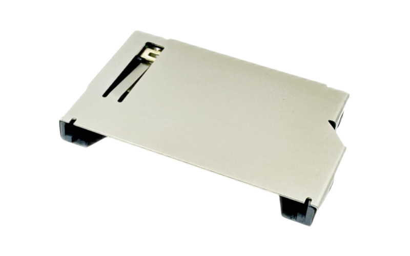
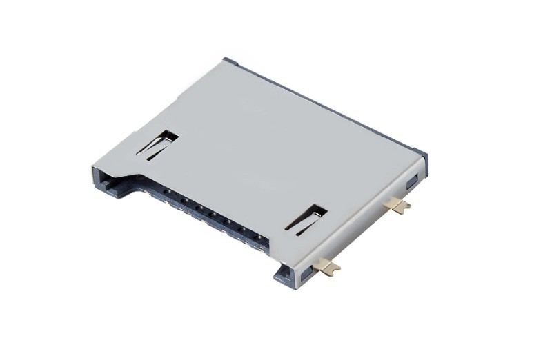
At Moarconn, our SD connectors are engineered with optimized terminals and reinforced solder tails, ensuring strong and consistent PCB assembly.
3. Signal Integrity and Trace Routing
High-speed applications such as SD Express and UHS-II demand careful signal routing to maintain integrity.
Recommendations:
Keep trace lengths short and matched
Control impedance with reference ground planes
Avoid vias directly on pads
Moarconn’s SD connectors are designed for stable signal transmission, even in high-speed cameras, drones, and IoT gateways.
4. Mechanical Stability and Reinforcement
Frequent insertions require mechanical stability to avoid long-term failures.
Best practices:
Use anchor pads or through-hole pegs for reinforcement
Align connectors with PCB edges for easier assembly
Add stiffeners for rugged environments
Moarconn connectors feature reinforced housings and stainless steel shields, perfect for automotive and industrial applications.
5. Thermal and Environmental Considerations
Thermal stress and harsh environments can shorten connector lifespan if not properly addressed.
Tips for designers:
Choose high-temp plastics such as LCP
Verify lead-free reflow soldering compatibility
Apply conformal coating for humidity protection
Moarconn uses high-temperature plastics and gold-plated contacts to guarantee durability in extreme conditions.
6. Partnering with Moarconn for Reliable SD Connectors
Designing a footprint is only half the work—the quality of the connector itself is decisive.
At Moarconn, we offer:
Wide range of SD/microSD connectors (push-push, push-pull, hinged)
OEM customization for specific PCB layouts
Rigorous quality testing for insertion cycles and durability
Fast support and global delivery
Conclusion
Optimizing the PCB footprint and layout of SD connectors ensures long-term reliability and high performance. Each design decision matters—from pad geometry to environmental resistance.
By choosing Moarconn, engineers and OEMs gain access to premium connectors, expert support, and dependable supply—helping products reach the market faster and more reliably.
Learn more at www.moarconn.com