Why Nano SIM Card Connector Reliability Matters
Why Nano SIM Card Connector Reliability Matters
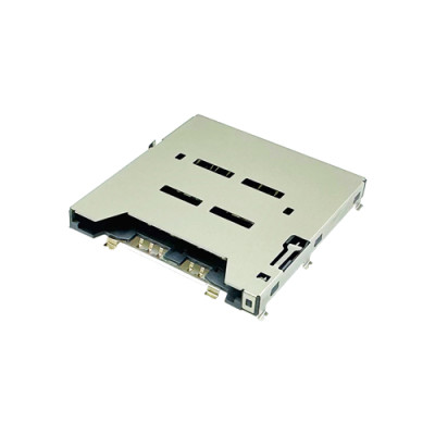
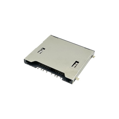
A Nano SIM Card Connector is a small component, but its reliability can determine whether an entire connected device maintains stable cellular communication.
In smartphones, industrial IoT equipment, vehicle telematics, smartwatches, security devices, communication equipment, and portable electronics, the connector provides the physical and electrical interface between the Nano SIM card and the host device. When that interface becomes unstable, the symptoms can appear at the system level: a SIM card may not be detected, network connectivity may become intermittent, or a device may experience unexpected communication failures.
The engineering challenge is that many Nano SIM connector failures do not originate from one obvious defect. They can result from the interaction of:
Contact plating and contact force
Spring geometry and fatigue
SIM card and connector tolerances
Housing material and dimensional stability
SMT soldering and PCB warpage
Card insertion and ejection mechanisms
Dust, moisture, oxidation, and corrosion
Vibration, shock, temperature, and humidity
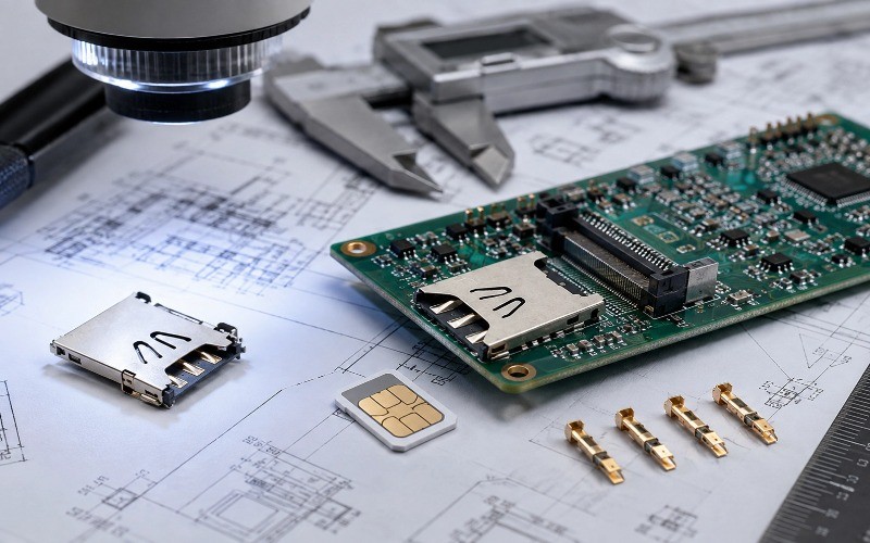
Moarconn's engineering experience shows that reliable Nano SIM Card Connectors need to be evaluated as part of the complete mechanical, electrical, and manufacturing system—not simply as an individual component. Moarconn has more than 20 years of card connector R&D and manufacturing experience and provides customized SIM, Nano SIM, SD, Micro SD, and smart card connector solutions.
What Makes a Nano SIM Card Connector Reliable?
Before discussing failure modes, engineers should define what “reliability” means for a Nano SIM connector.
A reliable connector needs to maintain its required performance across its expected operating life and environment.
1. Electrical Reliability
The connector must maintain stable electrical contact with the Nano SIM card.
Important parameters include:
Contact resistance
Contact stability after cycling
Insulation resistance
Electrical continuity
Resistance to oxidation and contamination
An increase in contact resistance can eventually cause unstable communication or SIM detection problems.
2. Mechanical Reliability
The connector must withstand repeated insertion, removal, vibration, shock, and mechanical stress without excessive deformation or loss of contact force.
Important considerations include:
Contact spring force
Mating and unmating cycles
Card retention
Ejection mechanism durability
Housing strength
Dimensional stability
3. Environmental Reliability
A Nano SIM connector may operate in environments involving:
High and low temperatures
Humidity
Vibration
Shock
Dust
Corrosive contaminants
The connector's materials and structure must remain stable under the actual conditions expected in the finished product.
4. Manufacturing Reliability
A connector that performs well in the laboratory can still fail after mass production if the PCB footprint, soldering process, dimensional tolerances, or assembly conditions are not properly controlled.
This is why connector reliability should be considered from design through mass production, rather than tested only after a problem occurs.
7 Common Nano SIM Card Connector Failure Modes
Failure Mode 1: Contact Wear and Poor Electrical Continuity
One of the most common Nano SIM connector problems is unstable electrical contact.
A device may initially recognize the SIM card correctly but develop intermittent connectivity after repeated insertion and removal, vibration, or environmental exposure.
Why Does Contact Failure Happen?
Several factors can contribute:
Insufficient or uneven contact plating
Contact surface contamination
Oxidation
Excessive mechanical wear
Insufficient spring force
Contact fatigue
Tolerance mismatch between the SIM card and connector
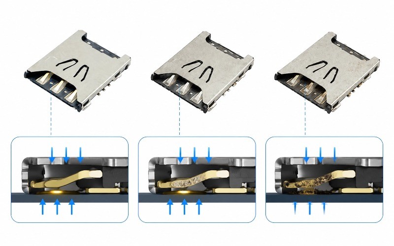
Repeated mating cycles can gradually change the contact interface. If contact force decreases or the contact surface becomes damaged or contaminated, contact resistance may increase.
How Engineers Prevent Contact Failure
A reliable design starts with the contact system itself.
Engineers should evaluate:
1.Contact material
2.Plating system
3.Contact geometry
4.Spring force
5.Contact travel
6.Expected mating cycles
7.Environmental exposure
Gold-plated contact surfaces can help provide stable electrical performance and resistance to oxidation when properly specified.
Moarconn's Nano SIM connector engineering approach incorporates gold-plated contacts, precision stamping, controlled spring geometry, and inspection processes to address these risks. Its published Nano SIM reliability guidance also identifies plating defects, weak spring force, contamination, and tolerance mismatch as important causes of contact failure.
Failure Mode 2: SIM Card Not Detected or Intermittent Connection
A common field symptom is:
“No SIM Card”
“SIM Card Not Detected”
Intermittent cellular connection
These symptoms do not automatically mean that the SIM card itself is defective.
The connector should be investigated as part of the failure analysis.
Possible Root Causes
Poor contact pressure
Contamination
Contact deformation
Card misalignment
Connector housing deformation
PCB warpage
Solder joint failure
Card detection switch failure
Moarconn's technical analysis identifies poor contact, oxidation, spring fatigue, and foreign-object contamination among the common causes of SIM connector detection problems.
Engineer's Diagnostic Sequence
When a Nano SIM card is not detected, a systematic approach is more effective than immediately replacing the connector.
Step 1 — Verify the SIM card
Test with a known-good Nano SIM card.
Step 2 — Inspect the connector
Check for:
Bent contacts
Contamination
Scratches
Deformation
Foreign particles
Step 3 — Check mechanical alignment
Verify that the card enters and seats correctly.
Step 4 — Check electrical performance
Measure:
Supply voltage
Signal continuity
Contact resistance
Relevant signal-line impedance
Step 5 — Inspect the PCB
Look for:
Solder cracks
Pad lifting
PCB warpage
Incorrect footprint
Assembly defects
This systematic diagnostic approach is consistent with Moarconn's published SIM connector troubleshooting methodology.
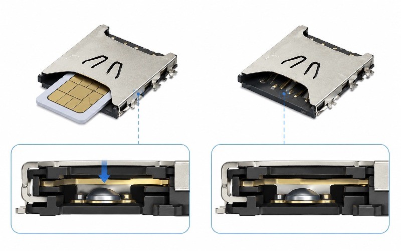
Failure Mode 3: Card Detection Switch Failure
Many Nano SIM Card Connectors include a card-detection function.
The switch tells the host system whether a card has been inserted.
This feature adds another mechanical and electrical interface that needs to remain reliable.
Common Causes
Excessive switch stroke
Metal-dome fatigue
Dust or contamination
Oxidation
PCB deformation after SMT
Mechanical over-travel
Repeated insertion cycles
A failed detection switch can create an unusual situation: the SIM card may have good electrical contact, but the host device still reports that no card is installed.
How Engineers Improve Detection Reliability
A robust design can include:
High-cycle detection switch structures
Controlled switch travel
Appropriate contact materials
Contamination-resistant construction
Mechanical protection
Reliability cycling during qualification
Moarconn's Nano SIM connector engineering information describes high-cycle card-detection designs and testing above 10,000 cycles for applicable designs.
Failure Mode 4: Housing Deformation and Dimensional Instability
The connector housing provides more than electrical insulation.
It establishes the mechanical position of the Nano SIM card and contacts.
Even a small dimensional change can affect:
Card alignment
Contact position
Contact force
Card insertion
Ejection
Mechanical retention
What Causes Housing Deformation?
Typical causes include:
Insufficient heat resistance
Incorrect injection molding parameters
Uneven cooling
Excessive reflow temperature
Material shrinkage
Mechanical stress
This is especially important for ultra-low-profile Nano SIM connectors because the available mechanical tolerance can be limited.
Material Selection Matters
High-temperature engineering plastics such as LCP can be suitable for connector applications where dimensional stability and reflow compatibility are important.
Moarconn states that its LCP injection molding process can achieve dimensional accuracy of approximately ±0.01 mm for applicable connector components.
For engineers, however, the important lesson is not simply “choose LCP.”
The correct question is:
Does the complete material and molding process maintain the required geometry throughout SMT assembly and the product's operating environment?
That distinction is important when qualifying a supplier.
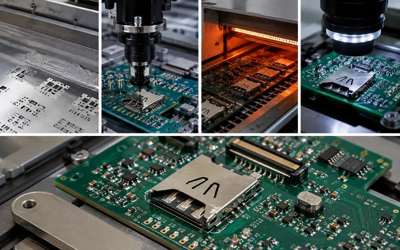
Failure Mode 5: SMT Solder Reliability
A high-quality Nano SIM Card Connector can still fail if the PCB assembly process is poorly controlled.
This makes SMT reliability part of connector reliability.
Typical SMT-Related Problems
Cold solder joints
Insufficient solder
Excessive solder voiding
Pad lifting
Solder cracking
Coplanarity problems
Connector misalignment
Incorrect reflow profile
Mechanical stress after assembly can be especially important.
For example, if the PCB flexes during device assembly or drop events, stress can be transferred directly to the connector solder joints.
How Engineers Reduce SMT Risk
Before production, verify:
Manufacturer-recommended PCB footprint
Pad dimensions
Solder mask design
Stencil design
Connector coplanarity
Pick-and-place orientation
Reflow profile
AOI inspection criteria
PCB mechanical support
Moarconn provides verified PCB footprints and 3D models for applicable connector designs to help engineers reduce design and assembly risks. Its published Nano SIM failure analysis also highlights coplanarity control, AOI, validated footprints, and reflow-profile control as important prevention measures.
Failure Mode 6: Misalignment, Pin Bending, and SIM Card Jamming
A Nano SIM connector must guide the card into the correct position.
If the mechanical tolerances are poorly controlled, the card may:
Enter at the wrong angle
Jam during insertion
Fail to reach the correct contact position
Damage the terminals
Become difficult to eject
Why Does Misalignment Occur?
Common causes include:
Poor tolerance stack-up
Inaccurate housing dimensions
Weak card guides
Poor tray design
Improper PCB positioning
Insufficient mechanical retention
Incorrect connector selection
Anti-Misalignment Design
Engineers can improve mechanical reliability with:
Card guides
Anti-misinsertion features
Card stops
Reinforced metal shells
Controlled terminal position
Mechanical fit testing
Moarconn's published Nano SIM connector engineering information describes anti-jamming guiding ribs, reinforced stainless-steel shells, mechanical fit testing, and optimized contact force as part of its approach to improving compatibility.
Failure Mode 7: Environmental and Corrosion-Related Failure
A connector operating in a controlled laboratory environment may behave differently in the field.
Temperature, humidity, vibration, and contamination can interact with mechanical and electrical factors.
High Humidity
Moisture can accelerate:
Oxidation
Corrosion
Contact degradation
Insulation resistance changes
Temperature Cycling
Repeated temperature changes can create differential expansion between:
Metal terminals
Plastic housing
PCB
Solder joints
Over time, this can affect mechanical dimensions and contact stability.
Vibration and Shock
Vibration can expose marginal contact designs that appear stable during static testing.
Potential results include:
Intermittent contact
Contact fretting
Mechanical loosening
Solder fatigue
For this reason, environmental qualification should be based on the actual application rather than relying only on room-temperature functional testing.
Moarconn's published SIM connector reliability work discusses temperature cycling, damp heat, vibration, shock, contact durability, and other qualification considerations
How Engineers Test Nano SIM Card Connector Reliability
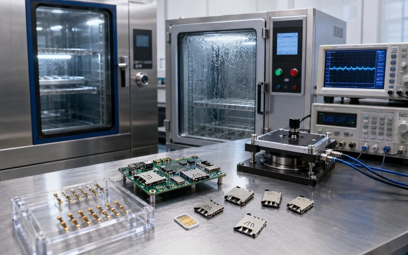
Reliability should be demonstrated through measurable tests rather than assumed from component appearance.
A practical Nano SIM connector qualification plan can include several categories.
1. Mating and Unmating Durability
Repeated insertion and removal simulates the expected mechanical life of the connector.
Engineers should monitor:
Contact resistance
Insertion force
Extraction force
Mechanical deformation
Detection-switch operation
Moarconn's published Nano SIM connector information cites 10,000–30,000 insertion-cycle testing for its applicable connector solutions.
Important: A cycle-life number should always be interpreted together with the test method, acceptance criteria, connector model, and application requirements.
2. Contact Resistance Testing
Contact resistance is one of the most useful indicators of electrical interface health.
Engineers should consider measuring:
Initial contact resistance → Resistance after cycling → Resistance after environmental exposure
A connector that maintains stable contact resistance throughout qualification provides stronger evidence of long-term electrical reliability.
3. Temperature Cycling
Temperature cycling evaluates whether the connector maintains its mechanical and electrical performance as materials repeatedly expand and contract.
A suitable test plan should reflect the actual application temperature range and relevant qualification requirements.
4. Damp Heat and Humidity Testing
Humidity testing helps evaluate:
Corrosion resistance
Contact stability
Insulation performance
Material compatibility
Moarconn's published SIM connector testing information includes a 85°C/85% RH damp-heat test for 1,000 hours for its applicable products.
5. Vibration and Shock Testing
These tests simulate real-world mechanical stresses experienced by:
Automotive equipment
Industrial equipment
Portable devices
Transportation systems
The objective is not simply to determine whether the connector breaks.
Engineers should also monitor whether vibration causes intermittent electrical discontinuity.
6. Visual and Dimensional Inspection
For miniature connectors, dimensional control is critical.
Inspection may include:
Terminal position
Housing dimensions
Coplanarity
Plating condition
Mechanical deformation
Molding defects
Moarconn reports using automated inspection and 100% CCD inspection for applicable contact-quality controls, supporting detection of issues such as scratches and plating defects.
Nano SIM Connector Reliability: From Failure Symptom to Root Cause
For engineering teams, a failure-mode table can be more useful than a general list of specifications
Failure Symptom | Possible Root Cause | Recommended Check | Design / Manufacturing Prevention |
| SIM not detected | Poor contact | Contact resistance test | Optimize contact force and plating |
| Intermittent connection | Contact wear or vibration | Cycling + vibration test | Improve contact geometry |
| Card detection failure | Switch fatigue | Detection-cycle test | High-cycle switch structure |
SIM card jams | Misalignment | Mechanical fit test | Improve card guides and tolerance |
Bent contact | Incorrect insertion | Visual inspection | Anti-misinsertion structure |
Housing deformation | Heat or molding stress | Dimensional inspection | Suitable high-temperature material |
Solder failure | Poor SMT process | AOI / cross-section | Validated footprint and reflow profile |
Corrosion | Humidity / contamination | Environmental testing | Appropriate plating and materials |
Increased resistance | Wear / oxidation | Resistance monitoring | Optimize plating system |
Failure after vibration | Insufficient retention | Vibration test | Reinforced housing and mechanical support |
What Engineers Should Check Before Selecting Nano SIM Card Connectors
Reliability should be part of connector selection—not something added after the design is complete.
Before approving a Nano SIM connector, ask the supplier for the following information.
Mechanical
Connector height
Card insertion mechanism
Card retention method
Insertion force
Extraction force
Mating-cycle rating
Terminal spring force
Mechanical tolerance
Electrical
Contact resistance
Rated current
Insulation resistance
Withstand voltage
Card-detection configuration
Contact plating specification
Materials
Contact material
Plating material and thickness
Housing material
Shell material
UL rating where applicable
Operating temperature
Manufacturing
Recommended PCB footprint
2D drawing
3D CAD model
Coplanarity specification
Reflow compatibility
SMT process recommendations
Inspection capability
Reliability
Mating-cycle testing
Temperature cycling
Humidity testing
Vibration
Shock
ESD where applicable
Contact resistance before and after testing
The most important point is to request test conditions and acceptance criteria, not only a statement such as “high reliability.”
How Moarconn Approaches Nano SIM Card Connector Reliability
For a connector manufacturer, reliability begins before the connector reaches the reliability laboratory.
It starts with design, material selection, tooling, stamping, molding, assembly, inspection, and qualification.
Moarconn has focused on card connector R&D, manufacturing, sales, and service for more than 20 years. Its current product and service portfolio includes SIM, Nano SIM, SD, Micro SD, and smart card connectors, along with customized connector development.
Precision Stamping and Molding
Moarconn's published Nano SIM engineering information emphasizes precision stamping and molding, with dimensional accuracy of approximately ±0.01 mm for applicable molding processes.
For Nano SIM applications, dimensional control matters because small deviations can affect:
Card alignment
Contact position
Contact force
Insertion performance
SMT assembly
Contact Quality Control
Moarconn reports 100% CCD inspection for applicable contact-quality controls, helping identify micro-scratches and plating-related defects before products move further through the manufacturing process.
Reliability Testing
For applicable connector designs, Moarconn reports 10,000–30,000 insertion-cycle testing and environmental reliability validation.
The exact qualification requirements should always be matched to the connector model and the customer's application.
Customized Nano SIM Connector Development
Not every device can use a standard connector.
Mechanical constraints may require:
Custom connector height
Special card retention
Different insertion mechanisms
Customized detection switch
Special PCB footprint
Reinforced mechanical structure
Application-specific environmental requirements
Moarconn's website currently lists customized Nano SIM card holder connectors and describes a development workflow covering requirement confirmation, quotation, product design, mold/fixture design, parts production, sampling, trial production, and mass production.
A Real Engineering Perspective: Reliability Is a System Property
One of the most important lessons from Nano SIM connector failure analysis is that the connector cannot be evaluated in isolation.
Consider a device that reports intermittent SIM detection.
The root cause might be:
Connector contact
→ contact wear
Mechanical structure
→ card misalignment
Material
→ housing deformation
PCB
→ warpage
SMT
→ solder cracking
Environment
→ humidity or vibration
System design
→ signal integrity or power sequencing
This means a reliable Nano SIM Card Connector requires coordination between connector design, PCB layout, SMT manufacturing, mechanical design, and system-level validation.
Nano SIM Card Connector Reliability Checklist
Before moving a Nano SIM connector into mass production, engineers can use this checklist:
Confirm the Nano SIM connector dimensions and mechanical envelope.
Verify the manufacturer's recommended PCB footprint.
Check connector height against enclosure clearance.
Confirm contact material and plating specification.
Verify contact resistance requirements.
Confirm insertion and extraction force.
Verify expected mating-cycle life.
Check card-detection switch requirements.
Evaluate card alignment and anti-misinsertion features.
Confirm housing material and operating-temperature range.
Review coplanarity and SMT requirements.
Validate the reflow profile.
Perform AOI after assembly.
Conduct contact resistance testing.
Perform insertion/extraction durability testing.
Evaluate temperature cycling where applicable.
Evaluate humidity exposure where applicable.
Perform vibration and shock testing for relevant applications.
Inspect connector deformation after testing.
Verify SIM detection after reliability testing.
Document failure modes and corrective actions.
Why Reliability Should Be Considered Before Supplier Selection
A low component price does not necessarily mean a low total cost.
A connector that saves a small amount during purchasing can become
significantly more expensive if it causes:
Assembly defects
Production downtime
Troubleshooting
Field returns
Product replacement
Customer complaints
Redesign
Requalification
For this reason, engineers and sourcing teams should evaluate a Nano SIM connector supplier based on more than unit price.
Consider:
Design capability + Manufacturing precision + Quality control + Reliability testing + Technical support + Customization capability
Moarconn positions its card connector business around these capabilities, including customized solutions, technical support, manufacturing, quality control, and after-sales service. The company also reports more than 1,200 successfully developed unique connectors and more than 150 global partners on its current website.